Login
If you can't access your account, please contact us.
![]()
![]()
![]()

|
FLYER |

|
TECHNICAL FLYER |

|
MANUAL - INDEX |

|
MANUAL - VIDEO |
OPLISMOS
Oplismos is an innovative graphic design software which can be used for the structural drawing of elements members (columns, walls, beams etc.) by a structural analyst.
Oplismos needs no further update or maintenance, because it is independent of any technical rules and standards.
Concrete and steel grades, their properties and technical characteristics (fck, fyk, fbd, Ecm, bar diameters, weight, bend diameters, rib height etc.), as well as safety factors, can be modified and the user is able to alter their values to see that they meet his demands.
For the development of the software, advanced problems of (algorithmic) analytical computational geometry were solved.
Οplismos aims to cover the needs of Structural Analysis Offices, Contractor Companies, Steel Manufacturing and Distribution Companies, Educational Institutions etc.
The software was initially developed to serve the needs of our office in order to achieve a higher level of rendering of our projects by producing accurate detail drawings and itemization of structural members (reinforcement tables, cutting length tables etc.).
The software's development was based on:
Α) The solution of (algorithmic) analytical computational geometry problems, that were required for the automatic drawing of structural details of the members' cross sections.
Β) Equations, algortihms, text and picture editing of the support material (information and technical flyer) as well as the software's testing, were designed by colleagues of our office who worked as analysts, software developers and software testers while at the same time, keeping up a close involement with our office's main activity, which is structural analysis.
The following office colleagues worked together to develop Oplismos:
Civil Engineers:
Takis Koumoulos, Dimitra Senegalia Koumoulou, George Koumoulos
Dimitris Aleksakis, Vasilis Papazisis, Sasa Vasilaki
Vallia Kotsira, Despina Nisidi, Katerina Bouba
Pavlos Georgopoulos, Sophia Vergini, Triantafyllou Dimitris, Leonidas Latsos
Scientific assistants providing programming, drawing, manual typing support etc.:
Evi Sotiriou, Stephania Stavropoulou, Mary Klapsi
Katerina Christianopoulou, Triantafyllou Dimitris, Zafiroula Polizogopoulou.
Addionally, the tasks mentioned below, were performed by our close colleague Katerina Christianopoulou:
1. Web design.
2. Manual and support material design (information, technical flyer).
3. Creation of instructional videos in which the technical flyer's material is presented, along with its applications.
Oplismos automatically creates:
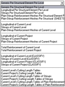
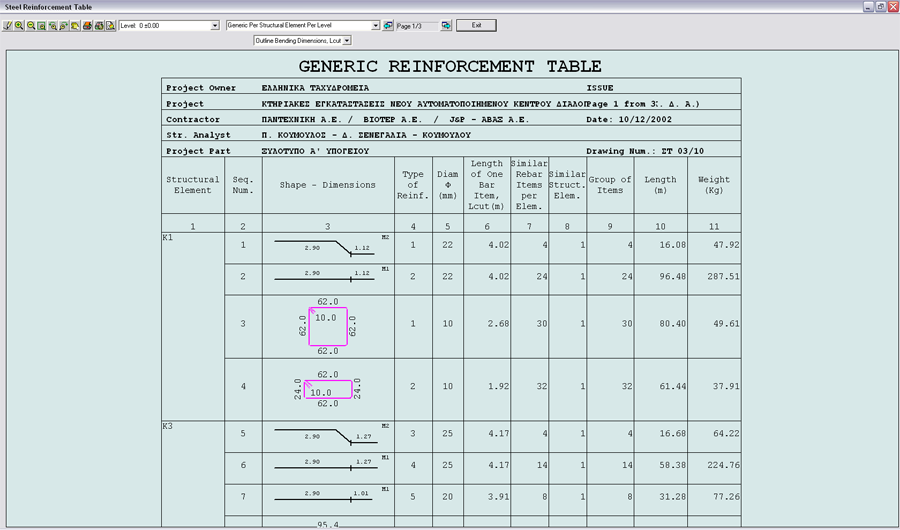
- Bar size tables per member, per level and project (17 table preferences in A4 or A3 print sizes).
- Cutting length tables per level and project, which are necessary during the reinforcement placement phase (6 table preferences in A3 or A4 print sizes).
- Bills of materials (concrete, reinforcement, framework area etc.).
Automatic calculation of the geometric properties of each member (moments of inertia, principal planes, radius of gyration, boundary coordinates which define the member's core etc.) for any of the following: concrete area (gross), concrete and steel area, Netto cross section and steel area. All of the above are necessary in structural modeling.
Precise drawings rendering of inertia ellipsoid and principal planes, convex cross section, core etc. of any cross section.
With Oplismos, you can easily redraw columns - walls - beams etc., their details, to meet analysis requirements, resulting from any structural analysis software.
Oplismos may prove a valuable ally, as it provides the contractor with reinforcement tables and cutting length tables of intermediate and final phases. It also allows one to produce As - Built drawings.
Additionally, it ensures an excellent cooperation between him and construction crews due to its accurate design of the project's elements.
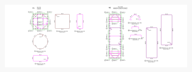
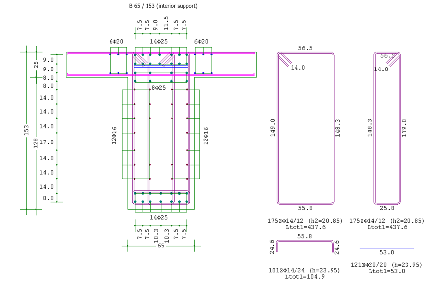
More specifically OPLISMOS deals with the design of:
Wall of a 7 storey building with 1 basement
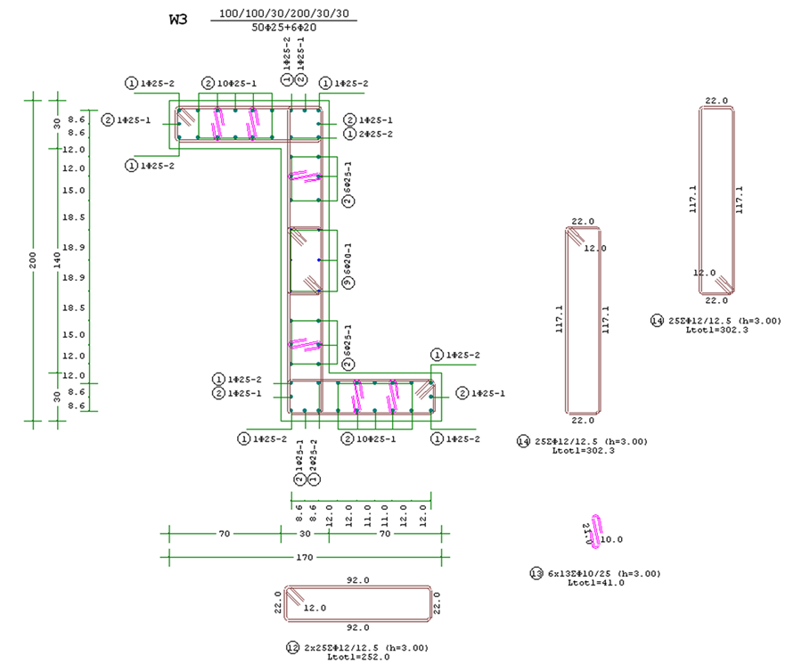
Column strengthening of "Hellenic Post SA." building
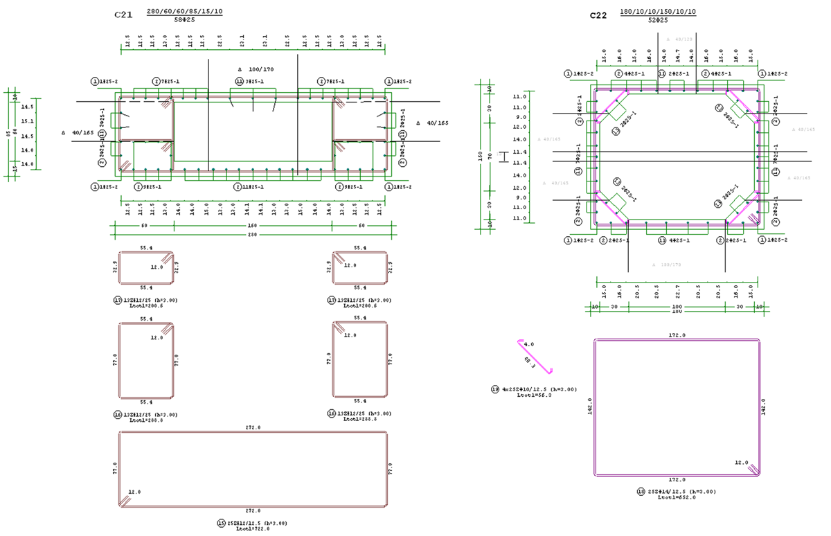
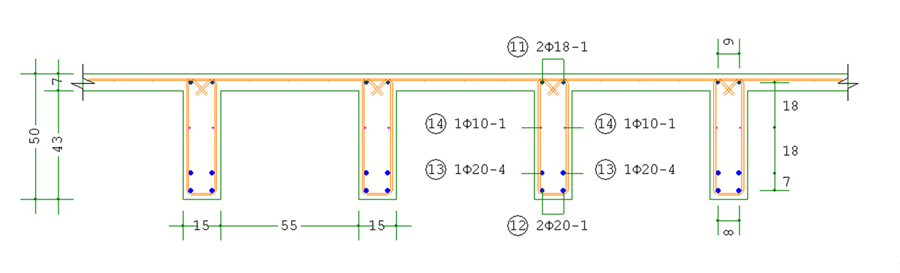
22.00 m span beam (Hellenic Post SA.)
(interior support)
Waffle Slab
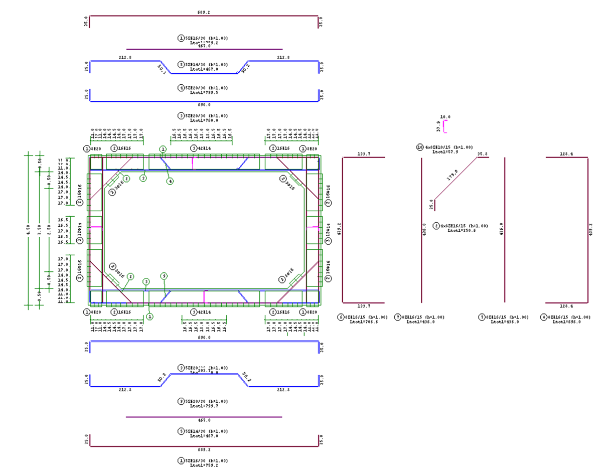
Concrete drainage structure 6.00 x 3.50 m
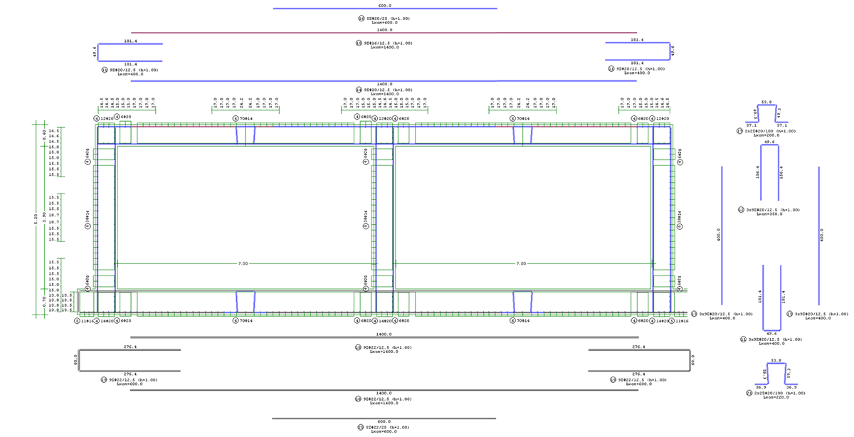
Twin concrete sewer 7.00 x 3.90 m
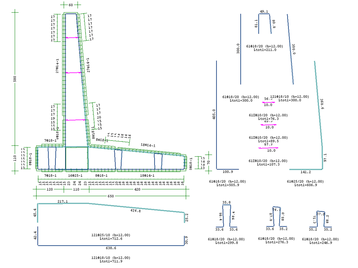
Retaining Wall
Composite Wall of an 8 storey building with 3 basements
How to work with OPLISMOS:
1. Insert the project's specifications (project' s title, contractor etc.), all materials used in the project (concrete and steel grades, bar diameters etc.), covers, ductility demand etc.
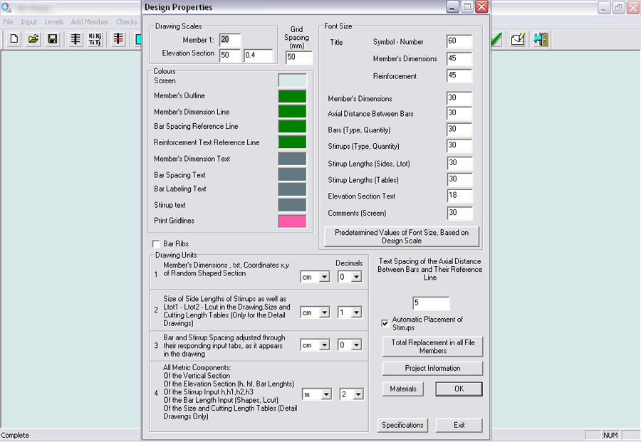
2. Insert all drawing parameters by defining scales (e.g. 1:10, 1:20, 1:50, etc.) and automatically or manually adjust font size to fit the desired scale and measurement units (m , cm, mm) etc.
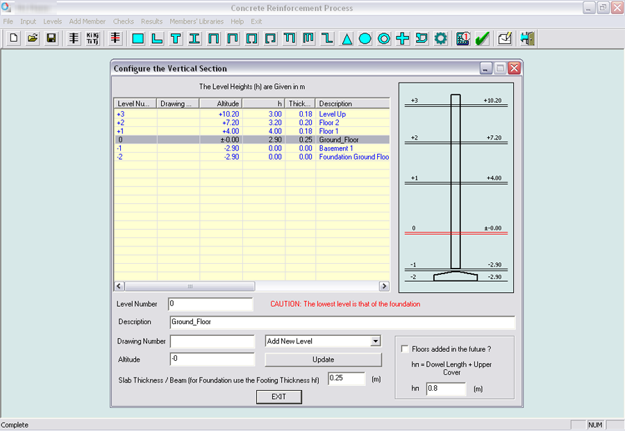
3. Insert the number and height of each level where all members will be placed upon.
  |
4. Select a member shape from a list of 19 typical shapes (rectangular, circular, Π - Shaped, Box Shaped etc.) and define its dimensions.
5. Design a member of any shape: a) by inserting the coordinates of its vertices or b) by importing a member directly from AutoCAD.
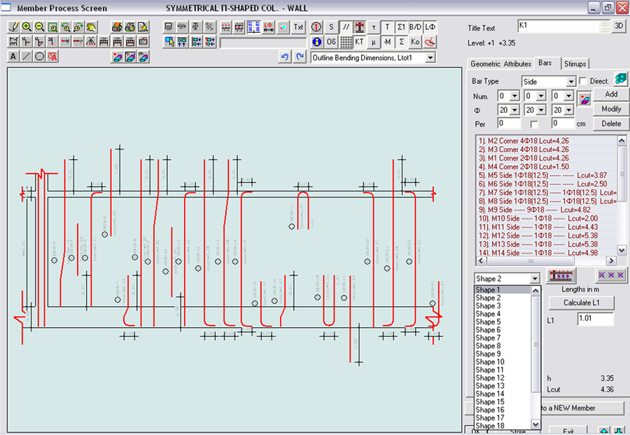
6. Original reinforcement placement of longitudinal bars, by defining their attributes (shape, diameter, quantity, spacing).
The available number of bars for use (straight, bent, etc.) is 23 and the user is able to create an infinite number of types per shape.
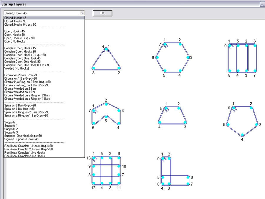
7. Original placement of any shape of stirrups, plain or stirrup reinforcement meshes, by defining their attributes (category, diameter, number, placement spacing).
The number of available stirrup categories (closed with hooks, open with hooks, open without hooks, circular, welded, etc.) is 36 and the user is able to create an infinite number of detail design types per category.
  |
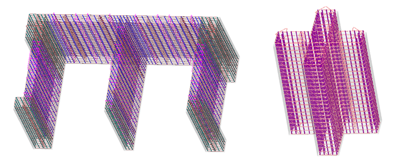
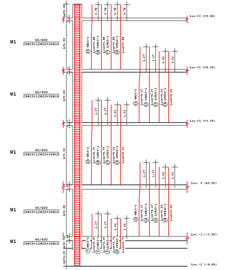
8. Three dimensional view (3D) of structural elements, which ensures immediate control over the desired reinforcement placement of bars and stirrups. Additionally, it becomes clear whether any practical placement difficulties might arise during construction phase due to a dense placement of bars (e.g. In a beam - column joint, or in the space where the dowels of the floor below, meet the bars of the floor above).
3D View of Composite Walls 3D View of Cross Shape member
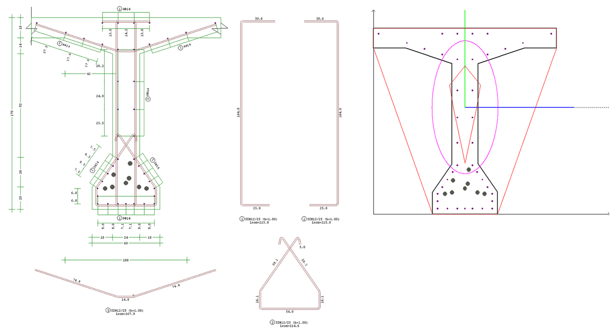
9. Ability to calculate geometric properties of any column, wall or beam member etc. (gross, netto etc.). Moments of inertia, principal planes, radiuses of inertia, coordinates which define the member's core, inertia ellipsoid, convex cross section and the member's core can be calculated automatically.
Calculation of geometric properties of each member is necessary in order to create a proper model of the structure. Furthermore, it provides the ability to solve composite problems in the field of Mechanics of materials (strength of materials.)
Primary prestressed beam of a 33.00 m span Beam's Geometric Properties
10. Ability to calculate bills of quantities (concrete volume, formwork area, reinforcement weight) directly for every member and the ability to automatically readjust them while designing the member and after every modification of dimensions or reinforcement.
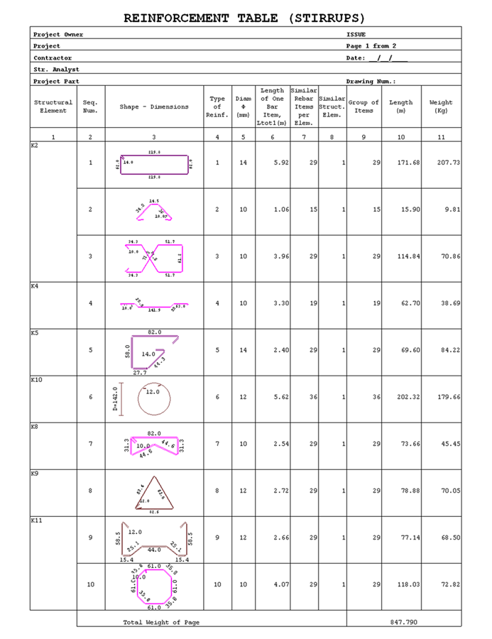
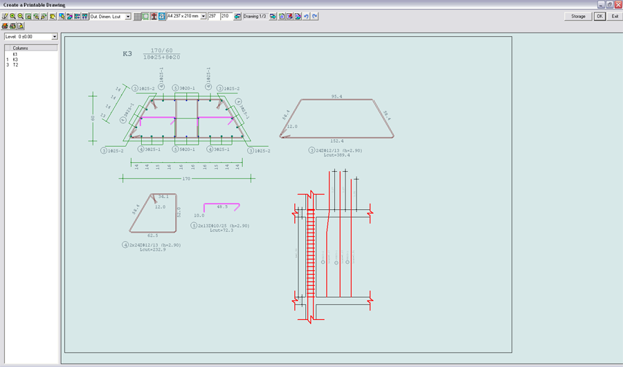
11. Automatic creation of reinforcement (bars, stirrups, plain - stirrup reinforcement meshes) tables, according to regulations per member, level and project.
During member design, the user is able to modify bar and stirrup lengths, in order to minimize costs and mitigate scrap metal.
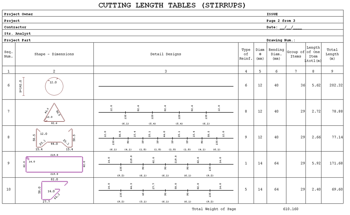
12. Automatically creates reinforcement cutting length tables (for reinforcement formed with automatic benders and reinforcement formed by hand), per member, level and project. It mainly concerns steel manufacturing and distribution companies. The reinforcement cutting length tables contain lengths, angles, bend diameter, arc lengths, total cutting lengths, etc. of the shaped reinforcement.
13. Provides a flexible way to prepare and print drawing sheets, depending on the demands of reinforcement detail drawings the user needs to present etc. Prints in colour are also available.
  |
14. Print reinforcement tables and drawing sheets.
Prints in colour are available.
15. Full interoperability between OPLISMOS and AutoCAD.
| Consecutively, OPLISMOS is self sufficient, because of its adaptability to any set of technical rules, old, current or new. |
Below is a list of only a few of the software's numerous features:
|
|
|
|
|
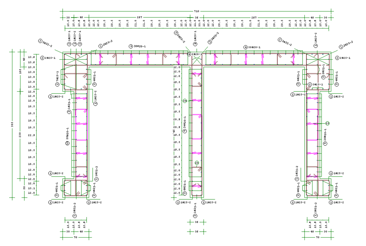
Total elevation section drawing of a column
1. The suggested maximum axial load NRd = (0.30 - 0.50) * fcd * Ac (for columns)
NRd = (0.20 - 0.35) * fcd * Ac (for walls) 2. The minimum percentage of reinforcement 4%ο per side of cross section, the maximum percentage 20%ο - 25%ο of reinforcement and the maximum concrete strain εC = 2.5%ο 3. For walls: i) 2%ο of the member's cross section, as the minimum percentage per side ii) pilasters within walls follow the regulations of columns, iii) 5‰ is the minimum percentage of reinforcement and εC = 2%ο the maximum concrete strain for the middle part of the wall. 4.The proper concrete laying which depends on the total placement of reinforcement bars in the dowel length area for columns, as well as the ability to create a column - beam joint. Members can be used for predetailing. |
|
NRd = 0.85 * fcd * Ac + fyd * As
as well as the suggested maximum axial loadNRd= (0.30 - 0.50) * fcd * Ac (for columns)
NRd= (0.20 - 0.35) * fcd * Ac (for walls) where NRd ≥ Νsd=1.35G + 1.50Q for the final design of the member (predetailing) according to our experience in seismic areas. |
|
|
|